PLL’s or phase locked loop

 
PLL is a feedback control system to generate an output clock frequency in phase to the input reference clock frequency. In other words its a closed-loop circuit that compares its output phase with the input reference clock phase and adjusts it in steps till the phases are aligned. This alignment of phase is termed as output clock phase is locked to input clock phase. This locked in phase relationship is termed as Phase Locked Loop or PLL.
 
Phase-locked loops (PLL) are crucial for modern-day electronic circuits. They are used to generate high frequency clocks from low speed clocks, phase synchronization of clocks, separate valuable signal information from noise and also used to demodulate amplitude and frequency modulated signals.

Follow this section for PLL’s in ASIC, FPGA configuration.

LTE - 4G Wireless Technology

Digital fundamentals.

Interview Questions.

The block diagram of PLL is discussed below.

PLL ASIC

The basic components of a phase-locked loop (PLL) are:
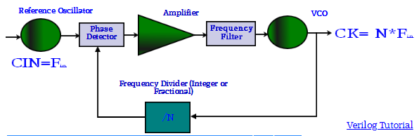
A Very accurate and stable Reference Oscillator, Phase Detector, Frequency Divider - Fractional or Integer, Voltage-Controlled oscillator (VCO), Amplifiers and Low Pass Filters.

PLL classification

Analog PLL :-
Analog components - VCO, loop filter (active/passive), and analog multiplier or analog phase detector
Digital PLL (DPLL) :-
Digital components - Digital phase detector (such as XOR, edge-trigger,JK, phase frequency detector), optional digital divider in feedback path.
Analog components - VCO, loop filter (active/passive)

All digital PLL (ADPLL)

Digital components - Phase detector, filter and numerical oscillator. Analog components - none
Software PLL (SPLL)
Software blocks are used.

Tutorials @fullchipdesign.com

Verilog Tutorial.

LTE Tutorial.

Memory Tutorial.

Hope you liked! this page. Don't forgot to access relevant previous and next sections with links below.